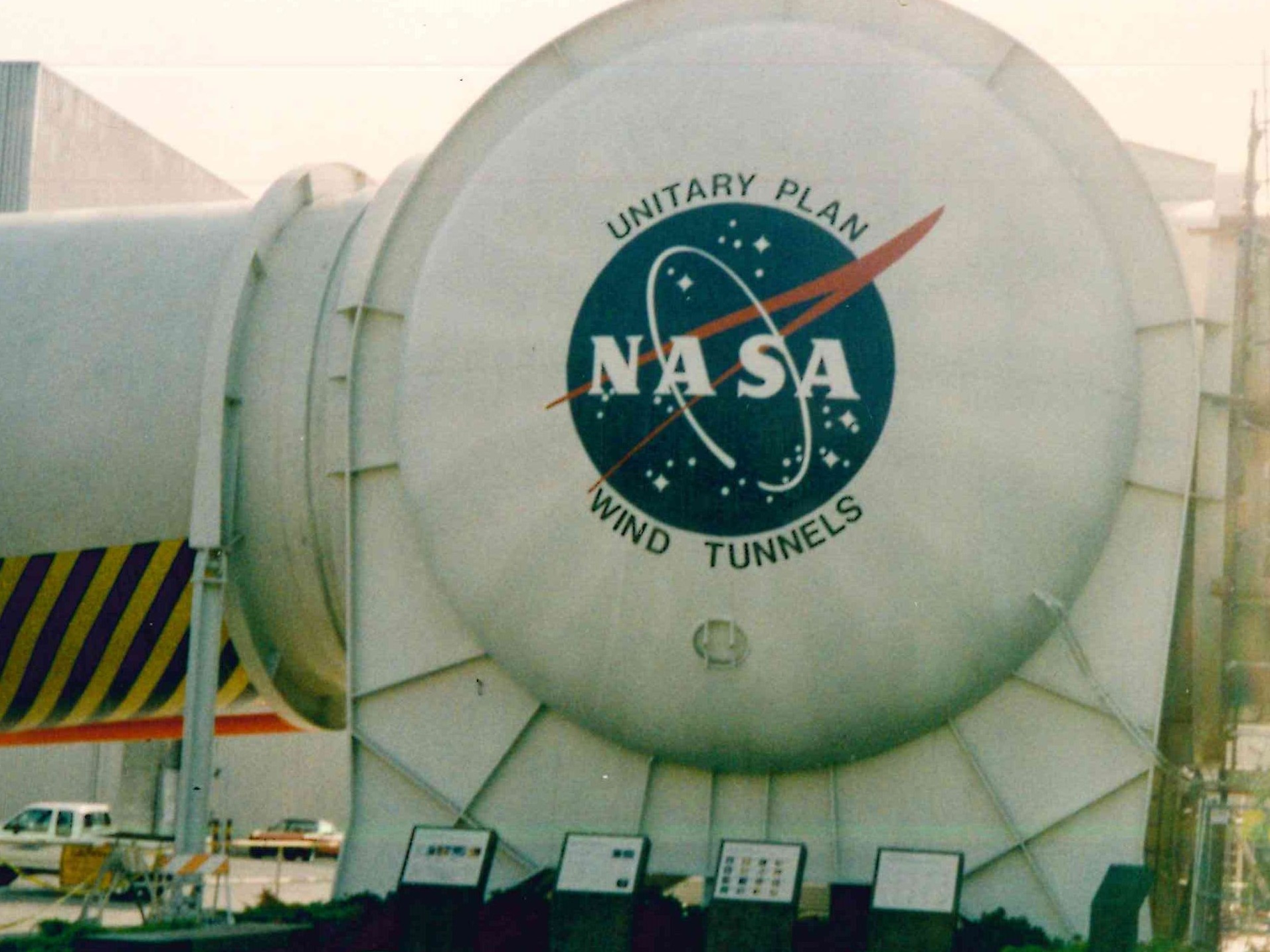
742, 5.7L Hemi Engines; that’s how many it would take to power the Unitary Plan Wind Tunnel. For nearly 30 years, EME has supported the electro-mechanical rotating equipment at NASA facilities across the nation, providing services ranging from small project consultation to large design and analysis efforts. One of the most challenging of these projects involved the Unitary Wind Tunnel Drive at the Moffet Field, California location, which is a unique machine capable of driving the large compressors employed by the wind tunnel in creating both sub and super-sonic airflow velocities.
Two interesting and complex projects associated with this critical equipment involved an uprate study for the Unitary Motor as well as development of the alignment process for the Rotor System. These projects demonstrated the importance of engineering expertise to resolve challenging issues for a critical customer’s equipment.
The Unitary Motor Up-Rate
The NASA AMES “Unitary” wind tunnel facility at Moffett Field is driven by four 45,000 hp wound rotor motors. Each motor is rated at 6900 volts for the stator winding and the wound rotors operate at 4370 volts. Through a number of projects, EME was engaged to evaluate the motors to determine if the motors could be up-rated, and if so, how much.
The initial condition assessment of the motor indicated that although they had never been rewound or refurbished they were in generally good condition. The next phase of the project involved determining how much of an up-rate could be achieved. Using our proprietary computer code, EMEINDUCT, we were able to come up with a design capable of over 80,000 hp at 7200 volts. Although the motor could develop this power, several pieces of the ancillary equipment could not support it. As a result, EME offered a different design solution which involved rewinding the unit with an increased ground wall thickness that resulted in a final rating of 60,600 hp – a 134% increase! These motors have now been in service successfully for over 20 years with the operating temperatures at the increased power as predicted.
Unitary Motor Drive Train Alignment Procedure
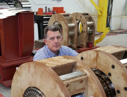
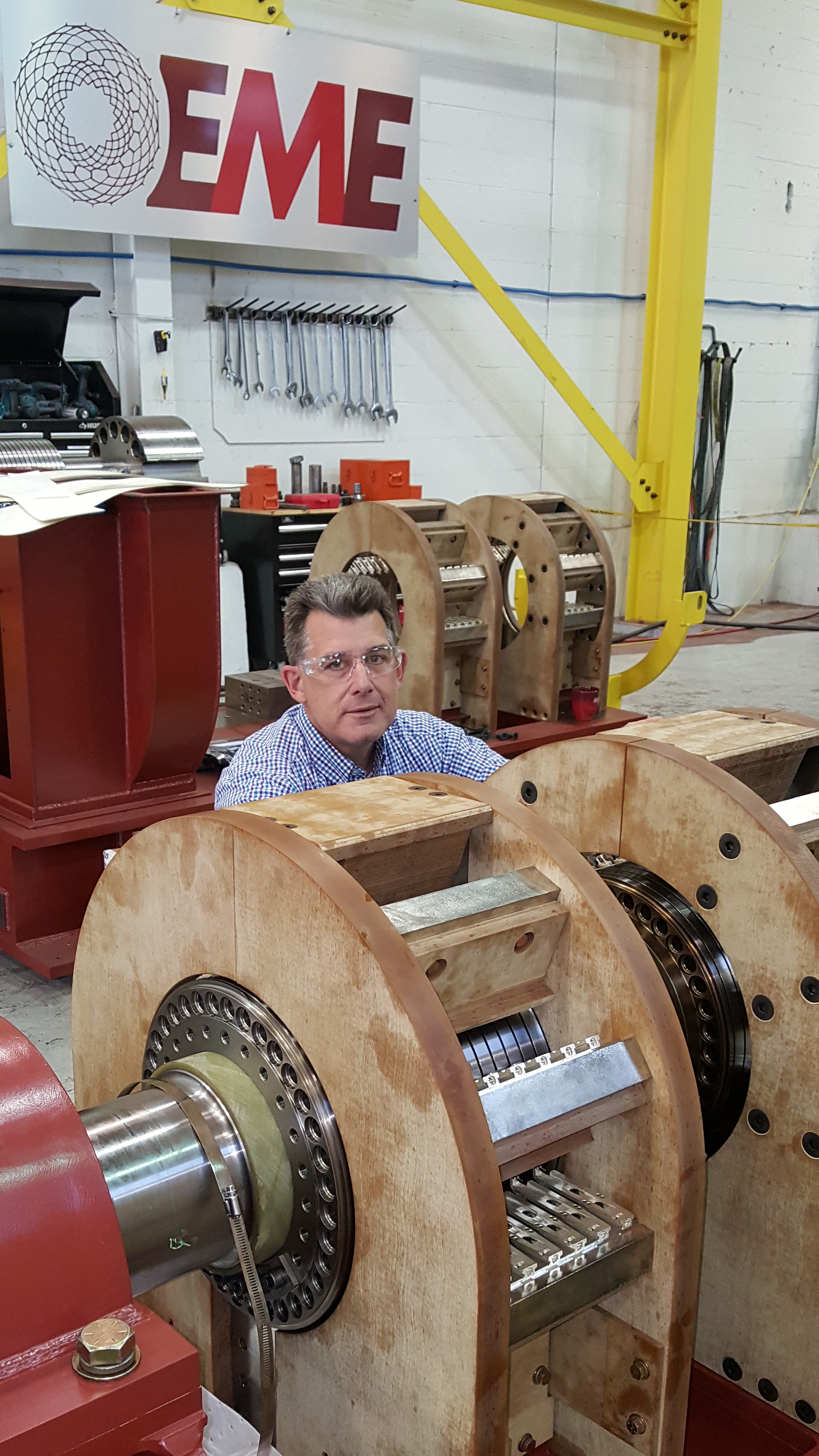
The Unitary Main Drive is comprised of four wound rotor electric motors, each rated at 60,000 horsepower at 690 rpm, on a common shafting system, approximately 107 ft. long, which is capable of developing 260,000 horsepower. The Unitary Main Drive is used to power either of two wind tunnel fans, or compressors, located at each end of the drive train. The Drive Train System is comprised of 3 shaft trains, and unique to this system are the two compressors on either end of the rotor train which are not moved as part of the alignment process.
Over time (and as a result of some earthquakes), the foundations had shifted such that the compressor shafts we slightly misaligned to one another, and at different elevations. Ultimately, this project entailed an in-depth study of the rotor and bearing system to determine how to optimize misalignment between machines (across the couplings) in order to share the load amongst the bearings, given their axial location within the train and load carrying capabilities.
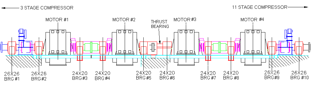
Unitary Drive Train (compressors at either end not shown)
The disconnect couplings on either end of the motor train provide for decoupling of either compressor, since only a single unit can be driven at any one time. Connection to the compressor is accomplished through sliding gear type couplings which are capable of transmitting more than 2,000,000 foot pounds of torque at 700 rpm. These couplings are very sensitive to misalignment and must be aligned to both shafts within .01 degrees, during both hot and cold operating conditions. This stringent requirement is the constraining factor in the whole system alignment, as the compressor shafts were not to be moved as part of this project scope.
Most alignment tasks consider only the matching of two machines, typically a driver (motor) and piece of rotating equipment used to perform work (pump, compressor, fan, blower, etc). For this situation, the criteria for alignment are only that the parallel offset and angular offset be reduced to an acceptable tolerance in order to minimize the forces transmitted across the coupling and into the adjacent bearings.
On long drive trains however, involving many bearings, with heavy rotors such as the Unitary drive train, the alignment method which has been used for many years involves the concept of ‘natural sag’ sometimes (incorrectly) referred to as the catenary curve (the curve a hanging flexible chain assumes when supported at its ends and acted upon by a uniform gravitational force). The principle is to allow each rotor and its associated shaft to assume a natural deflected shape due to dead weight. At the ends of each shaft, adjacent shafts are raised or lowered such that the elevation and slope across the coupling joints are matched. The actual shaft deflection, or sag, is what determines the elevation of each bearing. In this case however, as described previously, the compressor shafts were not to be moved. Therefore, the problem reduced to determining the proper elevation of each bearing within the train, such that the points on each end were fixed and the load sharing amongst the bearings was uniformly distributed.
To determine the proper elevation for each bearing, it was necessary to know the structural deflections and the local bending moments along the entire drive train, and to be able to predict any changes due to a change in the elevation at any bearing location. This unique blending of structural analysis and alignment criteria required both finite element modeling of the shafting, as well as a secondary mathematical model using influence coefficients to recalculate deflections, moments and coupling gaps for alignment purposes. Combining these two tools, EME developed a methodology, which would account for field conditions/measurements and allow for calculation of the proper bearing position to optimize operation of the rotor train; equally distribute bearing load, understand and manage resulting moments applied across coupling faces, and impacts to the cyclic bolt loading on the couplings.
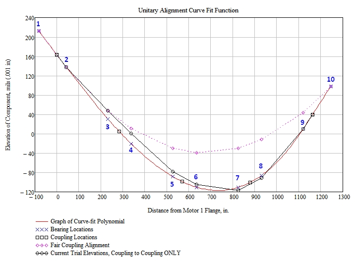
From the plot above, it can be seen that in the worst case, at bearing #7, a traditional “fair coupling” alignment would have placed the bearing at an elevation approximately 0.047inches too high, compared to the EME optimized alignment position; this alignment state would’ve have severely loaded the bearing and resulted in significantly reduced bearing life.


